
Prerequisite Modules:
- Development Software Suite
- Version Control
- Firmware System
- LED Basic
- Button Interface
- Debug Interface
- LCD_ASCII or LCD Dot Matrix
- ANT Introduction
- ANT Master
Start with the main Master code branch from the ANT Master module.
The program will do the following:
- Show if a channel is open and searching (green), paired (blue), loss of sync (blinking blue) and configured but closed(yellow)
- Display any NEW data from transmitting devices (repeated messages will be ignored)
- Respond to a special command that we define to set the backlight LED(s)
There are also some very important things to note:
- The default Broadcast message data for the ANTware Master is all zeroes except for the last byte which is a one-byte counter that increments every message (e.g. 00-00-00-00-00-00-00-xx)
- If you configure a Slave device with wildcard parameters, as soon as the Slave pairs with a Master the Slave will automatically update itself to the specific Channel ID of the Master. Even if the Slave channel is closed and then re-opened, the Channel ID will still be set to the last Master it paired with. There are very good reasons for this! If your application needs to reset back to wildcards, then simply resend the channel configuration message after the channel is closed.
- A Slave that is not paired will not provide regular messages to the host (unlike a Master that always sends messages at the Channel Period)
ANT_TICK and Events
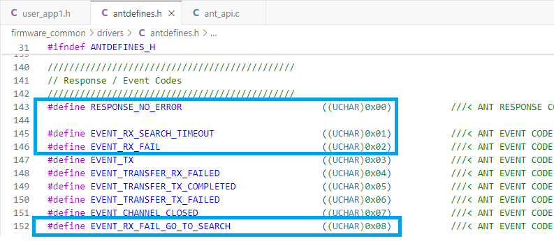
Once a Slave has paired, the status of the connection is continuously updated with events to the host. The events are defined by ANT and are provided in the antdefines.h header file. The ones we care about are shown here:
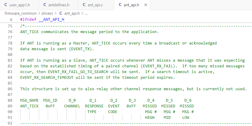
These events are forwarded to the application by ant_api through the ANT_TICK message. An ANT_TICK message is just an array of 8 bytes, but each byte is specified to mean something specific, per the definition in ant_api.h:
When processing an ANT_TICK message, you can index the 8-byte array with the following symbols so that your code is as readable as possible:
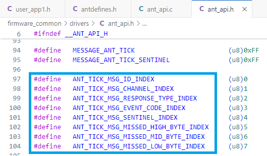
What is most important is to understand that the ANT_TICK message contains the EVENT_CODE at index [1]. The index is assigned the name ANT_TICK_MSG_EVENT_CODE_INDEX.
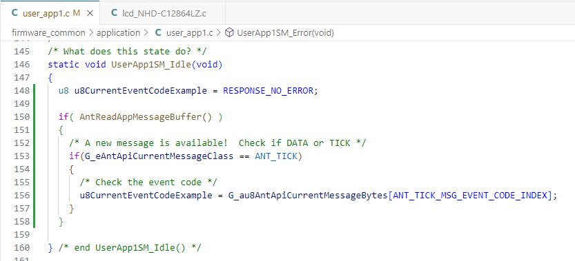
The 8 data bytes are presented to your application exactly the same way as they were presented in the ANT Master module, namely the global variable G_au8AntApiCurrentMessageBytes[8] that is updated when AntReadAppMessageBuffer() is called.
Therefore to get a copy of the current event code in an ANT_TICK message so you can react to it, the code in your task would look something like this:
Understanding the ANT_TICK message is absolutely essential, not only for the specific reason of looking at events, but because propagating information like this in an embedded system happens all the time. As a designer, you assign meaning to otherwise meaningless bytes and build an entire protocol on which your system works.
Initialization
To set up the user task, set the ANT channel parameters up with mostly wildcard values (wildcard = 0).
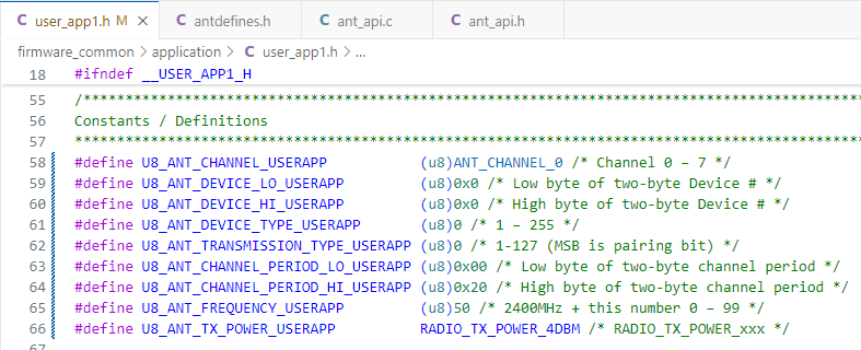
In user_app1.h:
#define U8_ANT_CHANNEL_USERAPP (u8)ANT_CHANNEL_0 /* Channel 0 – 7 */
#define U8_ANT_DEVICE_LO_USERAPP (u8)0x0 /* Low byte of two-byte Device # */
#define U8_ANT_DEVICE_HI_USERAPP (u8)0x0 /* High byte of two-byte Device # */
#define U8_ANT_DEVICE_TYPE_USERAPP (u8)0 /* 1 – 255 */
#define U8_ANT_TRANSMISSION_TYPE_USERAPP (u8)0 /* 1-127 (MSB is pairing bit) */
#define U8_ANT_CHANNEL_PERIOD_LO_USERAPP (u8)0x00 /* Low byte of two-byte channel period */
#define U8_ANT_CHANNEL_PERIOD_HI_USERAPP (u8)0x20 /* High byte of two-byte channel period */
#define U8_ANT_FREQUENCY_USERAPP (u8)50 /* 2400MHz + this number 0 – 99 */
#define U8_ANT_TX_POWER_USERAPP RADIO_TX_POWER_4DBM /* RADIO_TX_POWER_xxx */
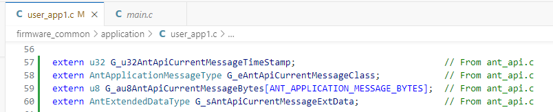
In user_app1.c:
Copy in the external global definitions from ant_api.c like you did in the ANT Master module.
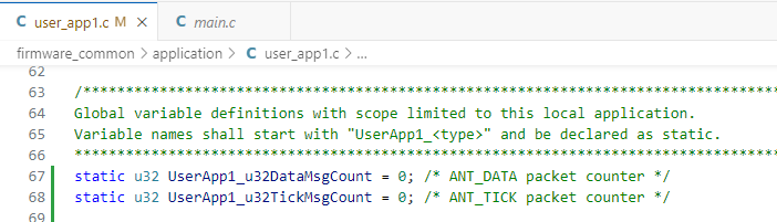
Also add some debug counters to your user_app that will be useful to see how the system is behaving:
Add code in UserApp1Initialize in the same way that was done for ANT Master (remember you can copy and paste the example sChannelInfo code from ant_api.c) . Make sure to use “CHANNEL_TYPE_SLAVE” for .AntChannelType. Include code to update the LCD message and start with the red LED on (use LED0 if you have a dot matrix dev board). Call AntAssignChannel if the check for good initialization and select either WaitAntReady or Error state based on the channel assignment message return value (this will be TRUE if the channel assignment request is ok).
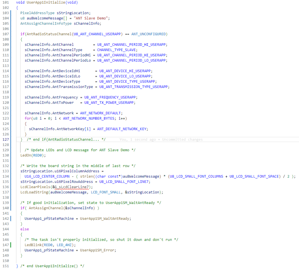
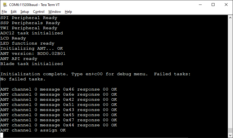
When the channel is configured, update the LED status and go to the Idle state. Build and test the code to this point. Watch the status LEDs – you should see the red LED turn on briefly before changing to yellow to indicate the channel is configured and the Idle state is active. Watch your debug output in TeraTerm as well to confirm the ANT channel assignment is successful.
The user_app1 state machine
Managing an ANT slave channel offers new challenges because the task must be able to react to different conditions depending on the ANT radio state that will change depending on whether or not an ANT Master device is present. Trying to manage everything in a single state would involve a lot of “if” statements and be difficult to follow.
The state diagram below shows how the system will progress through four main states. To keep things as clear as possible, the conditions that hold a state are not explicitly shown. The WaitAntReady state is also not shown.
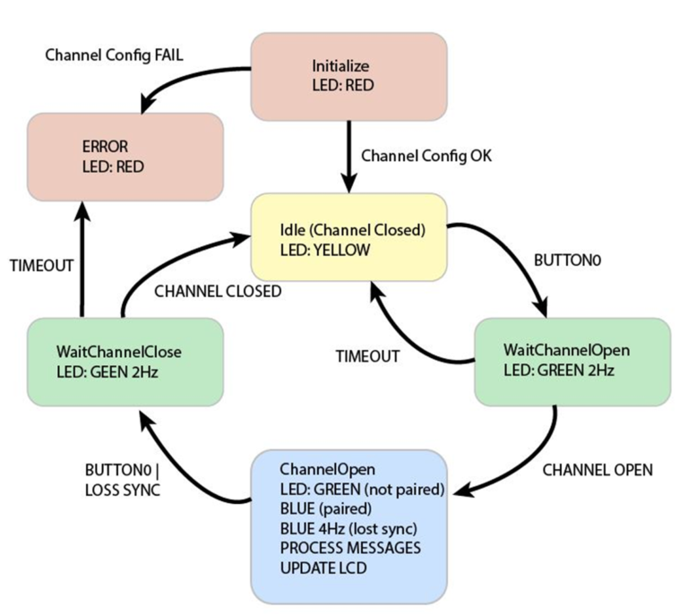
We can consider both the Idle and ChannelOpen states “steady states” since the radio is in a known state at those times and we expect a button press or other action to change states. That is not to say that things are not happening. In the ChannelOpen state, the system will continually be reading messages, monitoring the channel, and updating the LCD. WaitChannelOpen and WaitChannelClose are transitory states because we should never be there for more than about one second while ANT opens or closes a channel. Therefore both these states use a timeout counter to ensure the system does not get stuck while waiting for the external device to do something.
Hardly any of the possible problems that could come up are addressed in this example code. A robust system would handle every error case, provide debugging information, and do its best to get the radio back to a known, working state if anything went wrong. Of course that would require substantially more code and testing — something you would be expected to do if this were a commercial product.
To implement the new states, copy the following framework into user_app1.c and do not forget to add the required function prototypes in user_app1.h for each new state.
Idle State
This state looks for BUTTON0. When pressed, it queues OpenChannel(), sets up the LEDs for the next state, initializes the timeout counter and sets the state machine to execute WaitChannelOpen on the next cycle. In most cases, you always set up the static conditions for the next state as you exit out of the current state. Note the use of UserApp1_u32Timeout which is global to the task and provides timing between states.