
Prerequisite Modules:
- Development Software Suite
- Version Control
- Firmware System
- LED Basic
- Button Interface
- Debug Interface
- LCD_ASCII or LCD Dot Matrix
- ANT Introduction
This module will setup and run the development board in Master mode and communicate to an ANTware Slave. The user application will monitor the state of the buttons and update a field in the broadcast data corresponding to the button presses. When data is received, it will be printed to the LCD along with a received message count.
Branch the latest Master repository for the starting point. There are two layers in the EiE ANT stack: ant.c which is all the interface code to the nRF using the ANT protocol, and ant_api.c which is an abstraction to further reduce the complexity of using the ANT radio. The API should be sufficient for most of what you would do with ANT on the EiE development board, but don’t be surprised if you need to work at the ant.c level for certain things. You might add additional functions to ant_api.c to do that. Make sure you have the dev board debug output visible in whatever terminal program you are using so you can get ANT status messages.
ANT Initialization
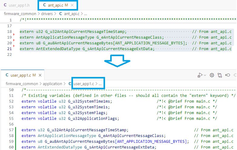
Follow the instructions in ant_api.c to setup and initialize an ANT channel in the user_app1.c task. The steps are shown below, starting with copying the required “extern” globals to user_app1.c
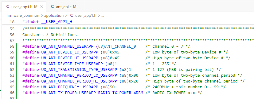
In user_app1.h, add the following definitions but update ANT_DEVICE_LO and ANT_DEVICE_HI to the last four digits of your ID number so it is unique. The text can be copied below and should appear in user_app1.h as shown.
#define U8_ANT_CHANNEL_USERAPP (u8)ANT_CHANNEL_0 /* Channel 0 – 7 */
#define U8_ANT_DEVICE_LO_USERAPP (u8)0x34 /* Low byte of two-byte Device # */
#define U8_ANT_DEVICE_HI_USERAPP (u8)0x12 /* High byte of two-byte Device # */
#define U8_ANT_DEVICE_TYPE_USERAPP (u8)1 /* 1 – 255 */
#define U8_ANT_TRANSMISSION_TYPE_USERAPP (u8)1 /* 1-127 (MSB is pairing bit) */
#define U8_ANT_CHANNEL_PERIOD_LO_USERAPP (u8)0x00 /* Low byte of two-byte channel period */
#define U8_ANT_CHANNEL_PERIOD_HI_USERAPP (u8)0x20 /* High byte of two-byte channel period */
#define U8_ANT_FREQUENCY_USERAPP (u8)50 /* 2400MHz + this number 0 – 99 */
#define U8_ANT_TX_POWER_USERAPP RADIO_TX_POWER_4DBM /* RADIO_TX_POWER_xxx */
Look at the function information for AntAssignChannel() in ant_api.c. Copy and paste the example setup code into UserApp1Initialize().
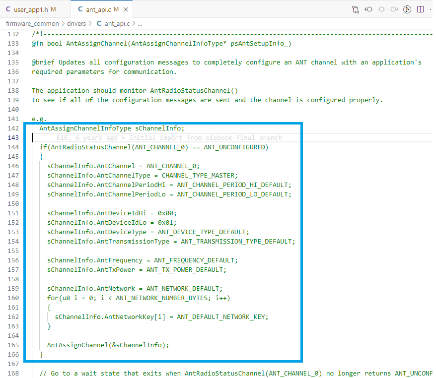
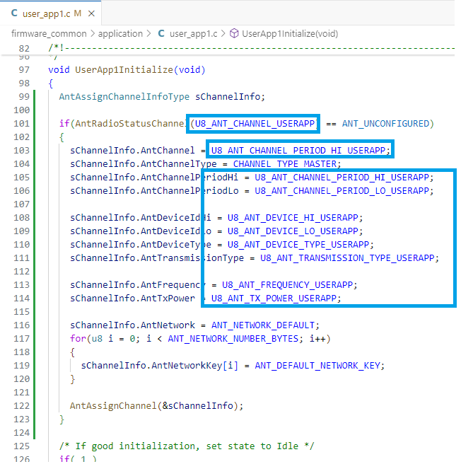
Replace the constants from the user_app1.h definitions entered in the previous step. Leave the AntChannelType and AntNetwork values unchanged.
The channel assignment messages are queued by AntAssignChannel() but are not sent immediately since the system state machine must run. The ant_api task will proceed to send out the configuration messages and reports back through the debug interface. AntRadioStatusChannel(ANT_CHANNEL_0) can be called to wait for the channel to be configured. Therefore, the User App should wait until the ANT is ready.
To do this, change the starting state to a new state called “UserApp1SM_WaitAntReady” instead of the usual Idle state. Note that copying the Idle state code and updating the text for the new state name is a fast way to add a state.
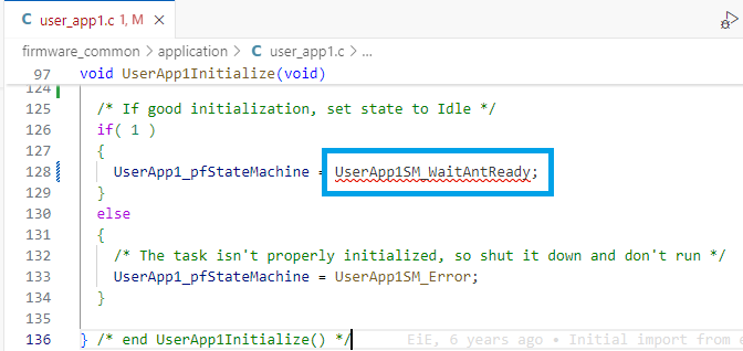
Add this state to the User App and write code to wait until AntRadioStatusChannel() returns “ANT_CONFIGURED” (see the function header for the return types). When this is true, call AntOpenChannelNumber() and move to the Idle state. Copying the Idle state code and updating the text for the new state name is a fast way to add a state.
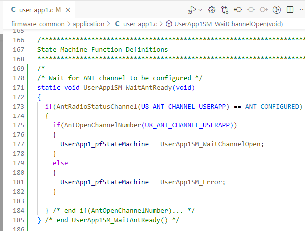
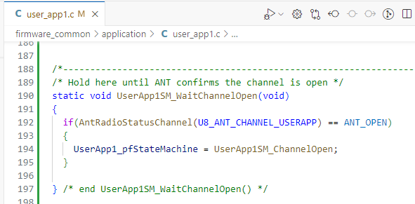
WaitChannelOpen() will again call AntRadioStatusChannel until “ANT_OPEN” is returned. At that point, you can enter the final state “UserApp1SM_ChannelOpen” where messages will be sent and received. What might stand out about what this example is lacking is that a good program would handle endless waiting or error states better, but for this example we’ll keep it simple.
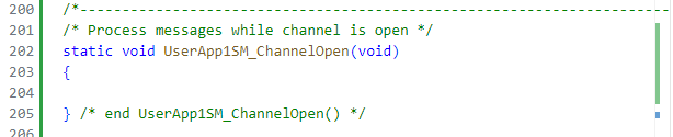
Add the final state UserApp1SM_ChannelOpen so the system is complete but leave the function empty for now.
Build the code just to make sure everything compiles without errors.
What might stand out about what this example is lacking is that a good program would handle endless waiting or error states better, but for this example we’ll keep it simple.
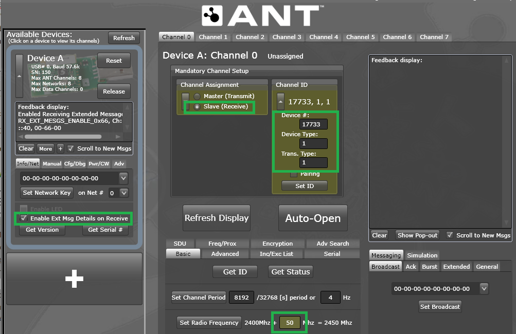
Set up ANTware to be listening on a slave channel configured to match the Master channel parameters you defined in your application. Do NOT use a scanning channel — you must use a “regular” ANT slave channel since we want to send data back to the dev board (which is not allowed with a scanning channel). In this example, the Device # is 0x4545 which is 17733 in decimal. Your Device # should be the last 4-digits of your student ID number.
Press the “Auto-Open” button when you have the Slave channel configured correctly in ANTware. Make sure your are monitoring the debug output in a terminal window.
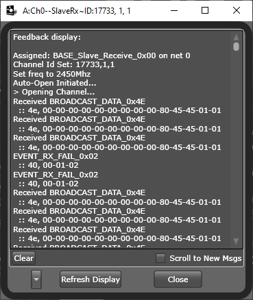
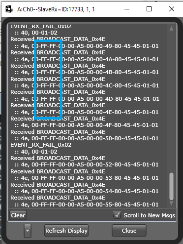
Build and run your code and watch the debug output and the ANT data window. Once the “Ant channel 0 open OK” message appears in the debug window, the data window in ANTware should show incoming BROADCAST_DATA_0x4E messages 4 times per second.
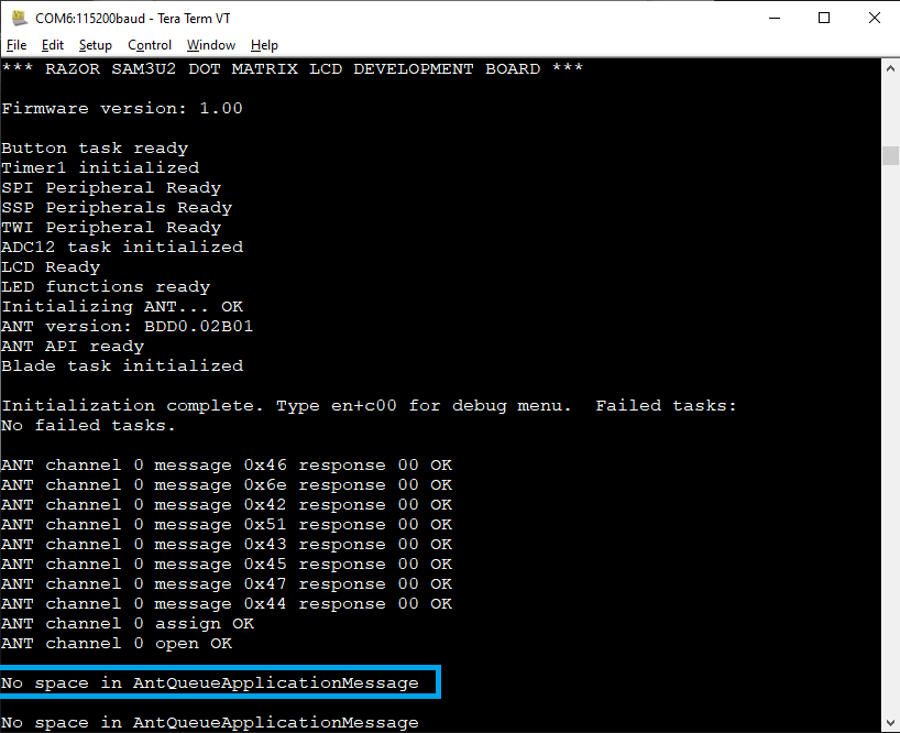
Wait for about 8 seconds after the dev board has been running – what do you see in the debug window and why?
Processing ANT messages
The ANT system ensures that the Master ANT channel ALWAYS sends a message at the channel period time when the channel is open – this is fundamental to the way the ANT radio protocol works. So even though we have not given ANT any data it starts sending data anyway. The default data packet is 00-00-00-00-00-00-00-00 which starts sending as soon as the “Open channel” function is called and the command is processed.
Whenever the ANT Master sends a message, a confirmation message is provided to the host (the EiE dev board processor) as an EVENT_TX message. This does NOT mean that the Slave received the message, just that the local Master ANT device sent the data. ANT can provide the host a variety of different messages and of course will forward data received, too, if anything comes back from the Slave to which the Master is paired.
The EiE ANT task tries to simplify all of this by collecting the messages, determining what they are, and then presenting them to the application as easily as possible through the API. This is done through a FIFO buffer that has space for 32 messages. Once the buffer is full, new messages will be lost so it is very important to always manage this buffer. Right now the system is broadcasting the default message and since we broadcast at 4Hz, it takes 8 seconds to fill up the 32 spaces. Once the buffer is full the board reports this out the debug interface.
Therefore, any ANT application you write should regularly process messages in the buffer to keep it from filling up. To check for a message in the buffer, call AntReadAppMessageBuffer() which will return TRUE if there is at least one message. If there is a message, AntReadAppMessageBuffer() loads the following variables with the oldest data from the buffer:
- G_u32AntApiCurrentMessageTimeStamp – the system time when the message was received.
- G_eAntApiCurrentMessageClass– the type of message (ANT_DATA or ANT_TICK) – more on this later.
- G_au8AntApiCurrentMessageBytes[] – the 8 bytes of message data.
- G_sAntApiCurrentMessageExtData – control data that might be useful later.
It is safe to call AntReadAppMessageBuffer() as many times as you want., though you must make sure to deal with the new data each time as it will be overwritten every call. This is exactly what you would want to do until it returns “FALSE” meaning it has no messages left to process. Since we can expect only one message every 250ms, calling it once per 1ms loop in your User App code is probably sufficient, though you cannot guarantee that and sometimes ANT will send more than one message. Never assume any timing based on how many messages are in the queue.
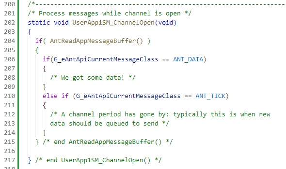
In UserApp1SM_ChannelOpen(), add code to check and handle a message. For now, set up the code to distinguish between an ANT_DATA and ANT_TICK message based on the value in G_eAntApiCurrentMessageClass if there was a message present.
Build and run the code and notice that you no longer get the “No space…” messages in the debug output. Although nothing is being done with the messages, the act of reading them clears them out and keeps the buffer empty.
Start the debugger which should come up halted at the start of main. Add the 4 global ANT data variables to the watch window. Expand the CurrentMessageBytes array and change to hex format view.
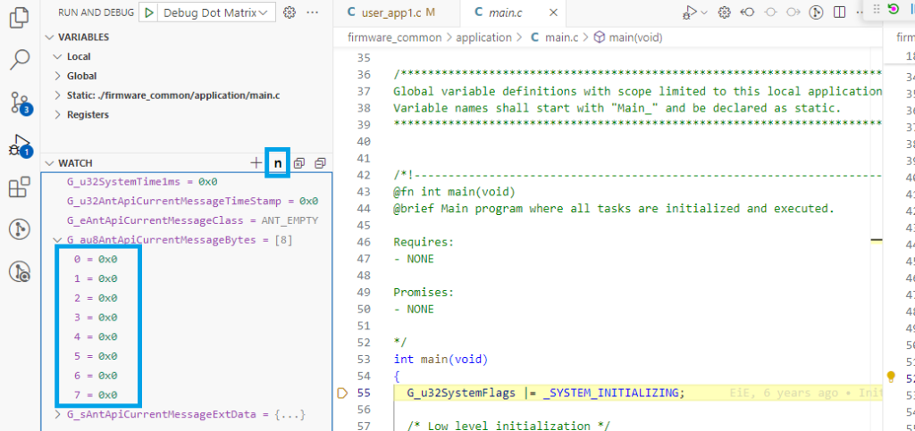
Start the code running. Once you see the “ANT channel 0 open OK” message from the debug terminal, place a breakpoint inside the code that will run when a new message is present (line 206 in this case). As soon as you do, the code should halt and the CurrentMessageBytes should update to values very close to what is shown below.
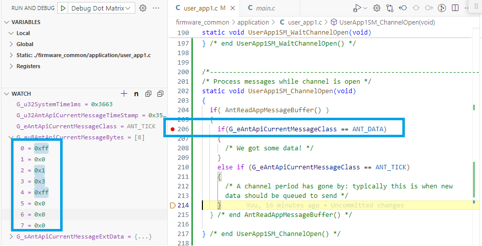
This is a very important debugging option for any ANT application you write, so be sure you understand what is going on. Since ANT will only be sending “ANT_TICK” messages right now, the CurrentMessageBytes or ExtData information is not really useful, but once ANT_DATA messages are coming in the debug information will be very useful so remember this process.
Remove the breakpoint and resume running the code. You should get some error messages on the Debug output, and the program might crash. This is because the ANT processor does not halt when the main processor is halted by the debugger.

In most cases of debugging ANT, you will send debug terminal messages to try to understand what is going on in your system as you probably do not want to disrupt the ANT tasks by halting the main processor. You can still use the debugger carefully to stop code at certain points to see what is happening at that moment, but most likely you will need to reset and re-run the code afterwards. This can still be very helpful, for example to look at the whole Ant_au9AntRxBuffer to see ALL the data that has come in (this buffer is circular, but fairly large so you can see a lot of data).
Sending data
Now you will give data to send over ANT. We are going to allocate the 8 bytes of the ANT data packet as follows:
- BUTTON0 STATUS
- BUTTON1 STATUS
- BUTTON2 STATUS (if using the ASCII dev board)
- BUTTON3 STATUS (if using the ASCII dev board)
- The constant 0xA5
- Message counter HI byte
- Message counter MID byte
- Message counter LO byte
If a button is pressed, the STATUS is 0xFF; if a button is not pressed, the STATUS is 0x00. The “message counter” simple counts how many times the message has been queued to send. How many messages can this counter keep track of?
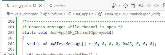
Set up a static array inside UserApp1SM_ChannelOpen() where the message will be constructed:
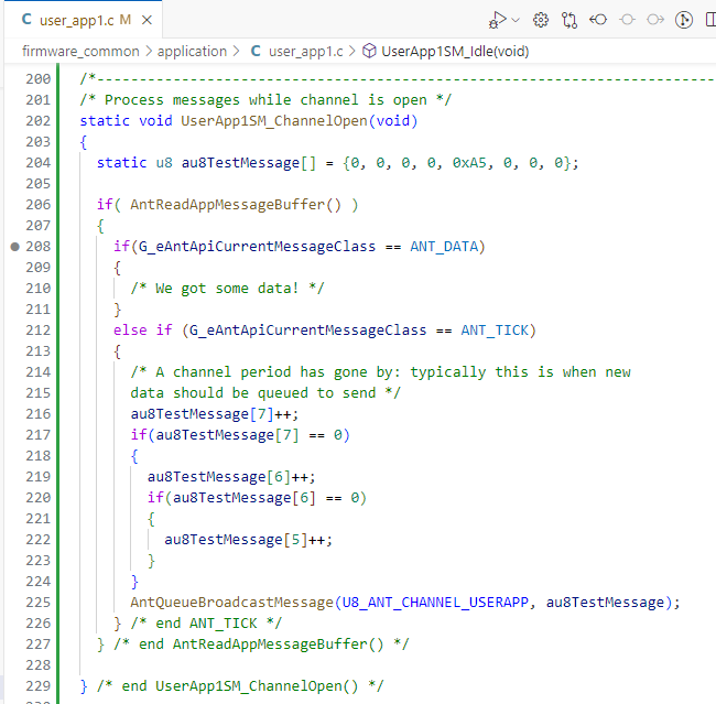
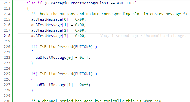
In the ANT_TICK message processing section, add code to manage the last three bytes in the array as the message counter and call AntQueueBroadcastMessage() to queue it to ANT (we will worry about the other bytes later). Make sure to correctly code the 3-byte counter to increment properly!
Build and run the code and make sure you observe the message counter increasing now in the ANTware data window. The data is shown in hex. The first “00” in the message is NOT part of the 8-byte data packet. The next 8 bytes are, so you can see four “00” that will hold the button status, the 0xA5 static value, and the 3 bytes of message counter. If you watch for at least 256 messages, you should see the middle byte increment. If you leave it running over night, you’ll eventually see the high byte increment.

Now add code to set the other bytes according to the current state of the buttons:
Build and test the code. Watch the message window as you press and release the different buttons. Notice the delay between pressing a button and when you see the data message change.
Receiving data
Now we can program handling data messages from ANT. There are two types of ANT data messages: Broadcast and Acknowledged. Broadcast messages are the most efficient as they are “fire and forget” from the sender’s perspective. Acknowledged messages cause the receiver to “ACK” the received message with a response. This occurs on the same channel period as the message was sent, so it requires extra power because the sender must activate its receiver to hear the response. However, there is nothing in the protocol to check whether or not the “ACK” was received (this is an endless chicken-and-egg problem to solve).
ANTware can send both types of messages. Remember that you cannot send data messages from ANTware if you are receiving on a scanning channel, so make sure you are opening a dedicated channel using the AUTO-OPEN button. Test that this is working by sending an “Acknowledged Data” message from ANTware. Even though the user application is not processing any data messages yet, the ANT protocol will automatically handle acknowledging messages.

So we know the system received the message. From the ANT API’s perspective, this would be an ANT_DATA message so add code in that section of user_app1 to parse out data into a nicely formatted string for display on the LCD. Since the ASCII and dot matrix dev boards offer a significantly different interface, code for each board is in separate sections here.
LCD ASCII ANT Data Display
Note this section is currently showing the code implemented in IAR but it should be simple to apply the steps in VS Code.
Start by defining a message placeholder and send this to the LCD (that’s 16 ‘x’ characters in the message). Build and run the code.

Set a breakpoint on LcdMessage(), build and run the code, and take a look at G_au8AntApiCurrentMessageBytes in a debug window when the code stops at the break point to see how the data sent from ANTware appears to the API. Make sure you see the matching numbers between the data you sent in ANTware and what appears in the data array.

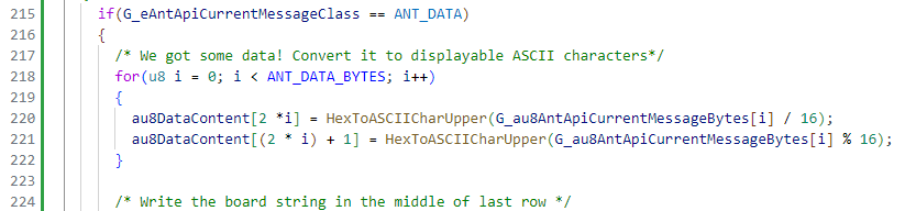
Write a loop to parse the hex values of each of the numbers into ASCII characters for the LCD display (each byte of the hex number must be masked off and converted to ASCII e.g. 0x41 is ‘4’ and ‘1’). Note there is a utility function called “HexToASCIICharUpper()” that might help. Alternatively, you could make it display the actual ASCII characters, but you’ll have to decide how to handle non-printable characters.

Practice sending different Broadcast and Acknowledged messages from ANTware to test the system. If everything is working well, consider yourself on the way to Mastering ANT Master!

Dot Matrix LCD ANT Data Display
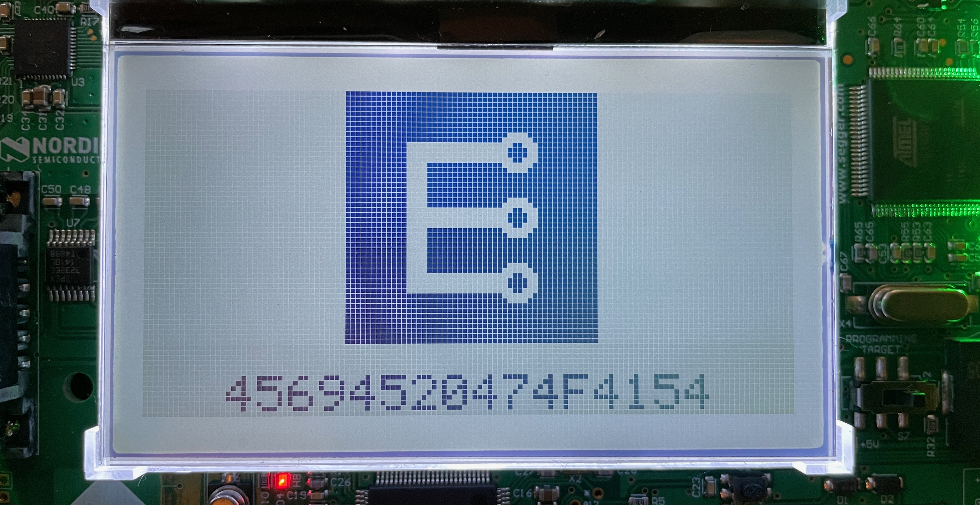
To keep this simple, the ANT message data will be displayed on the bottom LCD line in the same way that the ASCII data is displayed. You could, however, leverage the dot matrix LCD to provide additional information with formatting or headings.
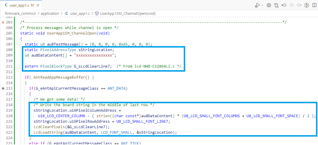
Start by defining a message placeholder and send this to the LCD (that’s 16 ‘x’ characters in the message). Recall that to write a line of text to the graphical LCD, you need to clear the line which requires a PixelBlockType parameter for the line, and then a PixelAddressType variable to set the location of the text. The LCD source code file has pre-defined PixelBlockTypes to clear lines of text which you can use if you make them visible with an “extern” definition. The example below recalculates the line position each time which isn’t necessary for a fixed-size string, but is included in case you decide to change the string size in some way.
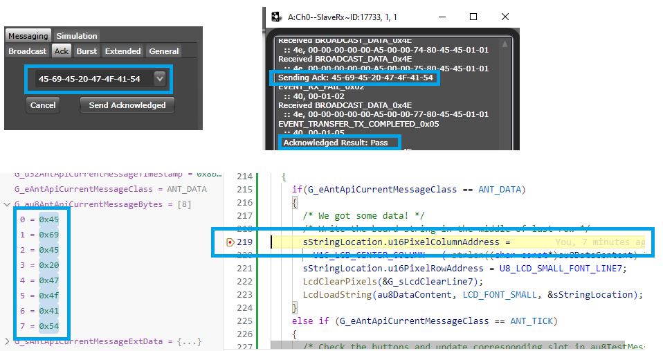
Build the code and start the debugger. Set a breakpoint inside the ANT_DATA section and run the program. Once the channel is open and you see the data streaming into ANTware, send an Acknowledged message from ANTware. Confirm that the message gets ACKed by looking for “Pass” in ANTware. This should also trigger the breakpoint and the code should stop in the ANT_DATA section. Take a look at G_au8AntApiCurrentMessageBytes in the debug window to see how the data sent from ANTware appears to the API. Make sure you see the matching numbers between the data you sent in ANTware and what appears in the data array. All of this is extremely important so do not move on until you have this working correctly.
Let the code resume running and you should notice the LCD text update to “xxx…” if that part of the code was written correctly.
Write a loop to parse the hex values of each of the numbers into ASCII characters for the LCD display (each byte of the hex number must be masked off and converted to ASCII e.g. 0x41 is ‘4’ and ‘1’). Note there is a utility function called “HexToASCIICharUpper()” that might help. Alternatively, you could make it display the actual ASCII characters, but you’ll have to decide how to handle non-printable characters.
Build and run the code (you don’t need to run in the debugger unless something is not working properly). Practice sending different Broadcast and Acknowledged messages from ANTware to test the system.
If everything is working well, consider yourself on the way to Mastering ANT Master!
[LAST UPDATE: 2025-JAN-23]